


Wire Mesh Cable Tray: Specifications, Applications and Selection Guide
Wire mesh cable trays provide an open support structure for routing and organizing electrical, control and communication cables. Their lightweight construction, visible cable routes and adaptable layout make them a practical option for many industrial, commercial and infrastructure installations.
Unlike enclosed cable trunking, a wire mesh cable tray uses a welded wire structure that allows air to circulate around supported cables and makes cable routes easier to inspect. Its suitability depends on the cable load, tray dimensions, support spacing, installation environment and applicable electrical requirements.
Bendin (Hebei Bendin Industrial Technology Co., Ltd.) supplies customizable metal products for industrial and infrastructure applications, including wire mesh cable tray solutions according to product availability and project requirements.
This guide explains wire mesh cable tray construction, typical specifications, material and coating options, load considerations, installation practices and selection criteria for industrial cable management projects.
1. What Is a Wire Mesh Cable Tray?
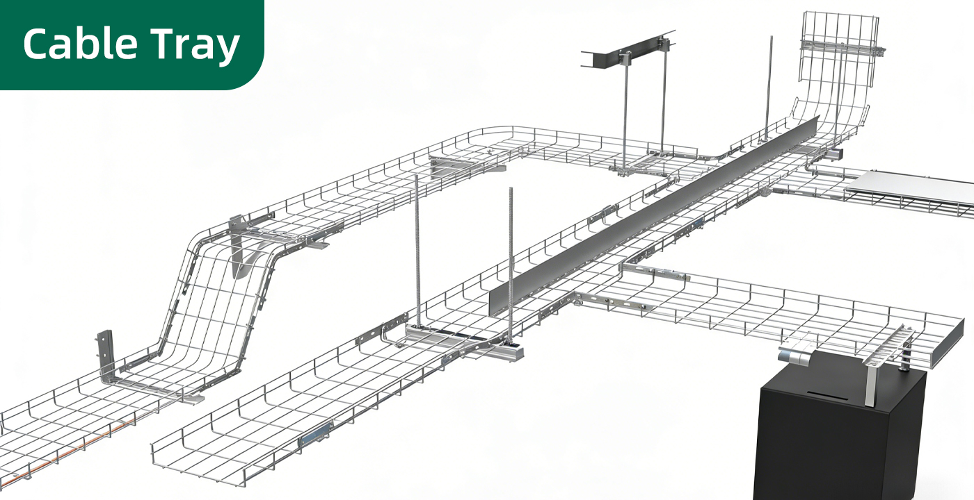
A wire mesh cable tray is a cable support system made from welded metal wires formed into a tray-shaped structure.
It supports cable routes along walls, ceilings, equipment areas and other suitable locations when installed with compatible supports and accessories.
A typical system may include:
- Welded wire mesh tray sections
- Connecting pieces and couplers
- Wall brackets and ceiling supports
- Suspension rods and support accessories
- Bends, tees and other compatible routing components
- Fasteners and mounting hardware
- Optional covers or protective accessories, where available
The exact configuration depends on the tray design, cable types, loading requirements, environmental conditions and installation method.
Wire mesh trays are commonly considered where accessibility and an open structure are important. They are not automatically suitable for every cable type or environment, particularly where additional mechanical protection, enclosure or specialized electrical separation is required.
2. How Wire Mesh Cable Trays Improve Cable Management
Open Structure and Airflow
The open mesh design allows air to circulate around cables more freely than some enclosed routing systems.
This may assist heat dissipation, but actual cable operating temperature depends on cable type, loading, installation density, ambient temperature and applicable electrical requirements.
Easier Cable Inspection
The visible structure makes it easier to inspect cable routes and identify changes, damage or areas requiring maintenance.
Technicians can often access cables without opening a continuous enclosure, subject to the installed configuration.
Flexible Routing
Wire mesh trays can be arranged around selected equipment layouts and cable routes.
Compatible bends, tees, connectors and support components help accommodate changes in direction. Any field modification should follow the manufacturer’s instructions and preserve the required structural and protective performance.
Convenient Future Expansion
When appropriately designed, accessible tray routes can make it easier to add or reorganize cables.
Future expansion still requires checking available capacity, cable separation, support loading and the applicable electrical installation requirements.
3. Wire Mesh Cable Tray Specifications
Cable tray specifications should be confirmed before ordering. The correct configuration depends on the cable schedule, installation route, support arrangement and environmental conditions.
Bendin can discuss customized configurations according to product design, manufacturing capabilities and project requirements.
| Parameter | Typical Options |
|---|---|
| Product Type | Wire Mesh Cable Tray |
| Main Material | Specified Steel Wire |
| Tray Width | Common options may include 50–600 mm, subject to product range |
| Tray Side Height | Product-specific |
| Wire Diameter | Product-specific |
| Mesh Opening | Product-specific |
| Tray Length | Standard or customized, subject to availability |
| Surface Treatment | Galvanized / Powder Coated / Other Specified Finish |
| Connecting Accessories | Compatible Couplers and Fasteners |
| Support Accessories | Wall Brackets / Ceiling Supports / Suspension Components |
| Routing Components | Compatible Bends, Tees and Other Fittings |
| Customization | Dimensions / Wire Specification / Finish / Accessories |
These are indicative configuration options, not guaranteed specifications for every product. Confirm the available widths, side heights, wire diameters, mesh dimensions and standard lengths before placing an order.
Tray Width and Side Height
Tray width determines the available cable-routing space. Side height affects the tray geometry and containment arrangement.
The selected dimensions should be based on the cable schedule, installation route, required cable separation and expected future expansion.
Wire Diameter and Mesh Dimensions
Wire diameter and mesh dimensions influence the structure and weight of the tray, but they do not independently establish its load capacity.
The complete configuration—including tray geometry, span, supports, connectors and installation method—must be considered.
Tray Length and Routing Accessories
Standardized tray lengths may simplify transportation and installation. Bends, tees, couplers and other accessories should match the selected tray system.
Before ordering, confirm the full route layout so that accessory quantities and installation interfaces can be planned accurately.
4. Materials and Corrosion Protection
Wire mesh cable trays may be installed in dry indoor spaces, humid production areas, outdoor routes or environments exposed to industrial pollutants.
The appropriate material and surface treatment depend on the product design, manufacturing process and operating conditions.
Galvanized Steel
Galvanized steel has a zinc coating that helps protect the underlying steel against corrosion.
Confirm the coating specification and manufacturing sequence for the selected tray. Where fabrication or cutting affects the coating, the required treatment should follow the applicable product instructions.
Hot-Dip Galvanizing
Hot-dip galvanizing provides a zinc coating that helps protect steel against corrosion.
The appropriate coating specification depends on the tray design, manufacturing process and environmental exposure.
Powder-Coated Finish
Powder coating provides a decorative finish and an additional protective layer when applied over an appropriately prepared substrate.
It may be selected where a specific appearance or color is required, provided the coating system is suitable for the operating environment.
Galvanizing Plus Powder Coating
A compatible galvanized substrate combined with powder coating may be suitable where both corrosion protection and appearance are important.
The coating system and manufacturing sequence should be confirmed for the actual product.
Environmental Selection Guide
| Environment | Main Considerations |
|---|---|
| Dry Indoor Areas | Material specification, cable loading and support spacing |
| Humid Workshops | Corrosion protection, drainage and inspection access |
| Outdoor Installations | Weather exposure, coating specification and support design |
| Coastal Locations | Airborne salt and increased corrosion risk |
| Industrial Areas | Possible exposure to pollutants, oils or cleaning chemicals |
| Data Centers | Cable organization, accessibility and coordination with facility requirements |
No coating system should be assumed suitable for every environment. Confirm the actual specification and maintenance requirements before ordering.
5. Load Capacity and Support Spacing
Load capacity is one of the most important considerations when selecting a wire mesh cable tray.
A tray must support the intended cable load without unacceptable deformation under the specified installation conditions.
What Determines Cable Tray Load Capacity?
Relevant factors include:
- Wire diameter and material properties
- Tray width and side height
- Mesh and tray geometry
- Distance between supports
- Connector design and location
- Cable weight and distribution
- Installation method
- Applicable design criteria
A tray made from thicker wire does not automatically have a higher permissible load under every configuration. The manufacturer’s load data must match the actual tray size and support arrangement.
Support Spacing
Support spacing affects the bending behavior of the tray and the load transferred to each support.
The required spacing should be selected according to the manufacturer’s technical data, the cable load and the installation design.
Do not apply a universal support interval to every tray size or loading condition.
Planning for Future Expansion
When a project is likely to add cables later, estimate both the initial and anticipated future cable loads.
Future capacity should be considered during the design stage rather than assuming that unused physical space alone guarantees additional load capacity.
6. Applications of Wire Mesh Cable Tray Systems
Industrial and Manufacturing Facilities
Factories use cable management systems to route power, control and communication cables between electrical panels, production equipment and automated machinery.
Wire mesh trays may be considered where accessible routing and a flexible installation layout are useful.
Commercial Buildings
Commercial buildings may use cable trays above ceilings, in service areas or in other suitable routes.
The selected system should be coordinated with building services, maintenance access and the applicable electrical design.
Data Centers and Communication Facilities
Data centers require organized cable routes to support equipment operation, inspection and future changes.
Wire mesh trays may be useful for selected cable routes, but tray selection should account for cable types, cable loading, routing requirements and the facility’s cooling and separation arrangements.
Airports and Infrastructure Facilities
Infrastructure projects may use cable trays for selected electrical and communication installations.
The tray system must match the environment, cable specification, support structure and applicable project requirements.
Industrial Control Systems
Control and instrumentation cables may require separation from other cable groups according to the system design and applicable requirements.
A tray layout should be planned around cable routing, access requirements and any required separation.
7. Wire Mesh Cable Tray vs. Other Cable Routing Systems
| Feature | Wire Mesh Cable Tray | Perforated Cable Tray | Solid-Bottom Cable Tray |
|---|---|---|---|
| Structure | Open welded wire mesh | Metal base with openings | Continuous metal base |
| Airflow | Open structure allows airflow | Depends on the perforation design | More enclosed base |
| Cable Access | Generally accessible through the open structure | Access depends on the installation | Access depends on the installation |
| Typical Selection Factor | Accessibility, routing flexibility and open construction | Supporting surface and ventilation requirements | Continuous base and specified cable-support requirements |
| Main Design Consideration | Wire structure, loading and supports | Tray dimensions, loading and supports | Tray dimensions, loading and any required cover or enclosure |
The most suitable cable support system depends on the cable types, environment, loading requirements, routing arrangement and applicable electrical installation rules.
8. Installation Best Practices
Correct installation helps maintain cable support, route organization and long-term accessibility.
Step 1: Prepare the Cable Route
Review the electrical layout and identify the route, changes in direction, equipment connections and maintenance access requirements.
Coordinate the route with other building services and structural components.
Step 2: Confirm Tray Specifications
Verify tray width, side height, wire diameter, mesh dimensions, surface treatment and required accessories.
Check that the selected tray configuration matches the cable schedule and expected loading.
Step 3: Plan Supports
Determine support locations according to the manufacturer’s data, tray configuration, cable load and mounting conditions.
Confirm that brackets, suspension components and anchors are suitable for the supporting structure.
Step 4: Install Tray Sections
Assemble the tray sections using compatible connectors and fasteners.
Check alignment and ensure that connections are installed according to the manufacturer’s instructions.
Step 5: Install Routing Accessories
Fit compatible bends, tees and other accessories according to the approved route.
Where field cutting or modification is permitted, finish the affected edges and restore any required protective coating according to the manufacturer’s instructions.
Step 6: Route and Secure Cables
Install cables according to the electrical design and the requirements for cable type, support, separation and bending radius.
Avoid exceeding the permitted load or overcrowding the tray.
Step 7: Inspect the Completed Installation
Check tray alignment, support stability, connector security, cable arrangement and access for future maintenance.
The installation should comply with the applicable electrical requirements and approved project documents.
9. Maintenance and Inspection
Routine inspection helps identify damage, corrosion or overloading before these issues affect the cable support system.
The appropriate inspection frequency depends on the environment, cable loading and project requirements.
Visual Inspection
Check for:
- Loose connectors and fasteners
- Deformed tray sections
- Damaged coating
- Visible corrosion
- Unstable supports
- Excessive cable accumulation
- Damaged cable insulation
- Obstructed access to inspection points
Cleaning
Remove dust and other contaminants using methods suitable for the material and operating environment.
Where industrial pollutants or corrosive deposits are present, follow the site’s approved cleaning procedures.
Repairs and Replacement
Damaged components should be assessed and repaired or replaced according to the manufacturer’s instructions and the applicable electrical safety requirements.
After modifying a tray route, confirm that the support arrangement and load capacity remain suitable for the revised installation.
Maintenance Records
For larger facilities, keep records of inspections, repairs and changes to cable routes. These records help track recurring issues and support future expansion planning.
10. Illustrative Project Example: Industrial Workshop Cable Routing
A manufacturing facility plans to organize power and control cables between an electrical room and several automated production lines.
The project team evaluates a wire mesh cable tray system to provide accessible routing and support for the specified cables.
Preliminary Configuration
| Item | Example Requirement |
|---|---|
| Application | Industrial Workshop Cable Routing |
| Tray Type | Wire Mesh Cable Tray |
| Tray Width | Selected according to the cable schedule |
| Side Height | According to the selected product |
| Wire Specification | Confirmed in the product specification |
| Surface Treatment | Suitable for the workshop environment |
| Support Spacing | According to the manufacturer’s load data |
| Connectors | Compatible Couplers and Fasteners |
| Routing Accessories | Bends and Other Components as Required |
| Inspection | Supports, Connections, Loading and Cable Arrangement |
Before installation, the project team confirms the cable quantities, expected load, support spacing, route layout and applicable electrical requirements.
This approach helps align product selection with the actual cable installation rather than choosing a tray based on dimensions alone.
This is an illustrative project scenario, not a completed Bendin customer installation.
11. How to Select a Wire Mesh Cable Tray Supplier
When comparing suppliers, evaluate the actual product specification and technical information rather than relying solely on general marketing descriptions.
Product Range
Confirm available tray widths, side heights, wire specifications, finishes and compatible accessories.
Technical Drawings
Request drawings showing tray dimensions, connection details and relevant installation interfaces.
Load Data
Request load information applicable to the selected tray size and support span.
Surface Treatment
Confirm the actual material, coating process and environmental suitability.
Component Compatibility
Verify that tray sections, connectors, bends, supports and fasteners are designed to work together.
Quality Documentation
Agree on inspection requirements and identify any relevant test reports or certificates.
Packaging and Delivery
Confirm product identification, packaging arrangements, shipment quantities and required export documents.
For customized projects, approve the final specifications and bill of materials before production begins.
12. Bendin Wire Mesh Cable Tray Solutions
Bendin supplies customizable metal products for industrial and infrastructure applications. Wire mesh cable tray configurations can be discussed according to product availability, manufacturing capabilities and project requirements.
Customization may include:
- Tray width and side height
- Wire diameter and mesh dimensions
- Tray lengths and routing components
- Compatible connectors and fasteners
- Support brackets and mounting accessories
- Surface treatment and finish
- Packaging and OEM requirements
Customers can provide cable schedules, routing drawings, installation conditions and technical specifications for review before ordering.
For projects requiring specific load performance or environmental resistance, the relevant requirements should be confirmed before the product configuration is finalized.
13. Frequently Asked Questions
What is a wire mesh cable tray used for?
It supports and organizes electrical, control and communication cables in suitable commercial, industrial and infrastructure installations.
Do wire mesh cable trays improve ventilation?
Their open structure allows air to circulate around cables. Actual cable temperature depends on the cable type, loading, installation density and environmental conditions.
Can wire mesh cable trays be used outdoors?
They may be suitable for outdoor installations when the material, surface treatment, supports and accessories are specified for the environment.
How do I select the correct tray width?
Consider cable quantities, cable sizes, routing requirements, applicable fill or separation rules and anticipated future expansion.
How do I determine the correct support spacing?
Use the manufacturer’s load data for the selected tray configuration and the actual cable load. Support spacing should not be based on a universal rule.
Are wire mesh cable trays waterproof?
Not necessarily. An open mesh tray is not a waterproof enclosure. Where environmental protection is required, assess the complete cable installation and any suitable protective measures.
Can Bendin customize wire mesh cable trays?
Customization can be discussed according to product availability and manufacturing capabilities. Confirm the required dimensions, wire specifications, finish and accessories before ordering.
14. Request a Wire Mesh Cable Tray Quotation
Wire mesh cable trays provide an accessible cable support structure for many industrial, commercial and infrastructure applications.
The correct configuration depends on tray dimensions, wire specifications, cable loading, support spacing, surface treatment and installation conditions.
Bendin (Hebei Bendin Industrial Technology Co., Ltd.) welcomes inquiries from international distributors, contractors, system integrators and project owners.
For a quotation, provide:
- Intended application
- Tray width and side height
- Required wire diameter and mesh dimensions
- Cable types and estimated loading
- Support spacing and mounting requirements
- Surface treatment and environmental exposure
- Required connectors and routing accessories
- Quantity and delivery destination
Bendin can review your requirements and discuss a suitable wire mesh cable tray configuration for your project.