


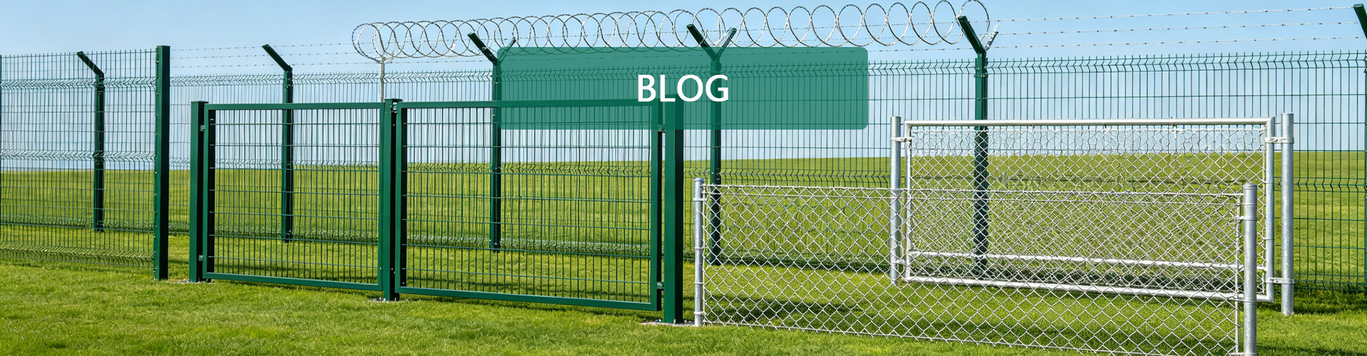

Integrated Industrial Safety Solutions: Fencing, Machine Guarding and Cable Management
Industrial facilities need more than individual safety products. External boundaries, machinery operating zones and electrical cable routes must all be planned according to their intended functions, installation conditions and applicable safety requirements.
When these systems are purchased and installed without sufficient coordination, projects may encounter incompatible components, blocked maintenance access, additional installation work and unnecessary operational interruptions.
An integrated approach helps coordinate perimeter fencing, machine guarding and cable management from the design stage through procurement, installation and maintenance.
Bendin (Hebei Bendin Industrial Technology Co., Ltd.) supplies customizable industrial fencing, machine guarding and cable management products for manufacturing plants, warehouses, logistics centers and infrastructure projects.
This guide explains how the three product categories work together, what technical information buyers should confirm and how to plan a coordinated industrial safety project.
1. Perimeter Protection: Establishing the External Boundary
Perimeter fencing defines the boundary of an industrial property and helps manage access between the facility and surrounding areas.
The appropriate system depends on the site’s security requirements, layout, environmental exposure and budget.
Common Perimeter Fence Options
3D bending fence
Welded mesh panels with V-shaped bends provide a structured boundary for general industrial and commercial applications.
Double wire mesh fence
Double horizontal wire reinforcement may be suitable where the selected panel design requires additional stiffness.
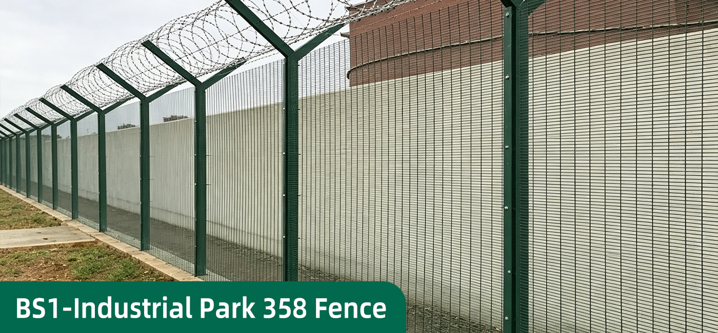
358 anti-climb fence
Dense mesh openings can make climbing and cutting more difficult than with many conventional open-mesh fences. This configuration may be considered for restricted-access facilities requiring enhanced perimeter protection.
Chain link fence
Woven diamond mesh may be suitable for long boundaries and selected outdoor applications where flexible installation is useful.
Key Selection Criteria
Before purchasing a perimeter fence, confirm:
- Fence height and total boundary length
- Mesh opening and wire diameter
- Panel dimensions
- Post profile and wall thickness
- Connection method and foundation requirements
- Gate positions and opening dimensions
- Surface treatment and color
- Environmental exposure
- Applicable project specifications
Steel grade and coating should be confirmed for the actual product. A particular material or surface-treatment process should not automatically be assumed to apply to every fence in a product range.
Coordinating Gates and Access Points
The perimeter plan should identify pedestrian entrances, vehicle gates, service routes and other required access points.
Gate posts, hinges, latches and foundations may require different specifications from intermediate fence posts.
Where access-control or surveillance equipment is required, its placement should be coordinated with the fence layout and site operating procedures.
2. Machine Guarding: Separating People from Hazardous Equipment
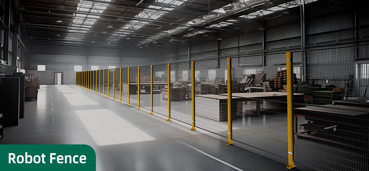
Machine guarding establishes a physical boundary around hazardous machinery and automated production areas.
It is commonly used around robotic workstations, conveyors, automated assembly lines and other industrial equipment.
Common Guarding Configurations
Full-mesh guarding
Welded mesh panels allow visibility into the guarded area while providing a physical boundary.
Mesh with solid lower panels
This configuration combines an open mesh section with a solid lower panel. Its suitability depends on the material or hazards that need to be contained.
Punched metal panels
Punched panels may be considered where a more enclosed appearance or specific opening pattern is required.
Modular access gates
Pedestrian and maintenance gates provide access for authorized personnel and equipment servicing.
Key Selection Criteria
When selecting machine guarding, confirm:
- Panel height and width
- Mesh opening and wire diameter
- Frame and post dimensions
- Mounting and fixing details
- Machine movement and operating envelope
- Maintenance access
- Gate positions and latching
- Compatibility with required safety interlocks
- Applicable machinery safety requirements
A physical guard is only one part of a machine safety solution. Where safety interlocks are required, the interlock and associated control functions must be suitable for the application and validated as part of the complete system.
Modular construction can simplify some layout changes, but modifications must preserve the required guarding distances and safety functions.
3. Cable Management: Organizing Electrical and Control Routes
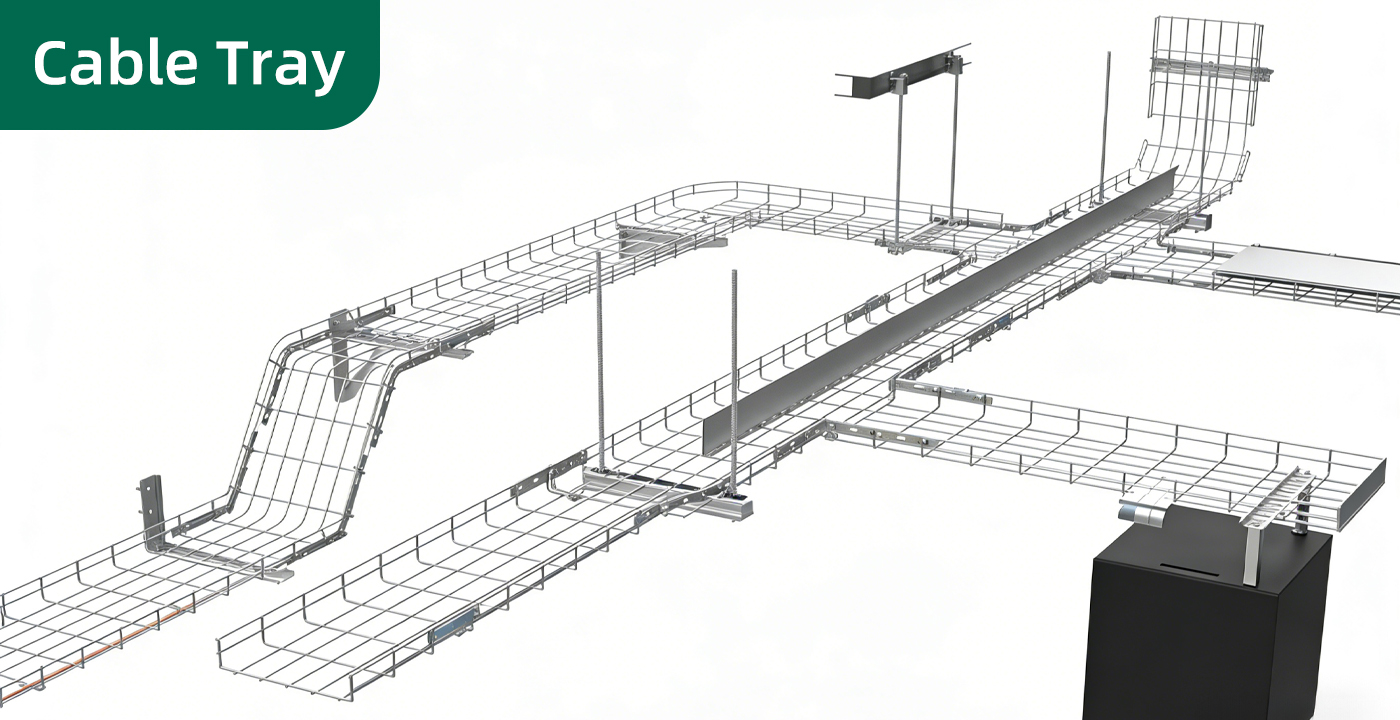
Cable management systems support and organize power, control, communication and instrumentation cables throughout industrial facilities.
A suitable cable routing system can improve accessibility for inspection, reduce exposure to mechanical damage and simplify future maintenance.
Common Cable Management Products
Mesh cable trays
Open-wire trays provide a ventilated supporting structure for compatible cable installations.
Perforated cable trays
Perforated trays provide a supporting base with openings that may assist ventilation and drainage.
Solid-bottom cable trays
Solid-bottom trays provide a continuous supporting surface for suitable cable installations.
Cable trunking
Cable trunking provides a more enclosed route for selected cable installations.
Key Selection Criteria
Before ordering, confirm:
- Tray type and dimensions
- Cable types and estimated quantities
- Total cable weight
- Support spacing and span
- Material and surface treatment
- Connection and mounting accessories
- Indoor or outdoor installation conditions
- Required cable separation
- Inspection and maintenance access
Tray capacity depends on the design, support arrangement, span, connections and loading conditions. Buyers should request applicable technical data for the actual configuration.
Cable trays help organize cable routes but do not eliminate all electrical hazards. The complete installation must follow the applicable electrical design and installation requirements.
4. Why Coordinate the Three Product Categories?
Although perimeter fencing, machine guarding and cable management serve different functions, their layouts can affect one another.
For example, a perimeter fence may obstruct a vehicle route, a machine guard may interfere with maintenance access, or a cable tray may conflict with a machine enclosure.
Coordinated planning helps identify these issues before manufacturing and installation begin.
| Product Category | Main Function | Coordination Requirement |
|---|---|---|
| Perimeter Fencing | Define external boundaries and manage access | Coordinate fence routes, foundations, gates and access roads |
| Machine Guarding | Separate people from hazardous machinery | Coordinate machine layouts, gates and maintenance clearance |
| Cable Management | Support and organize cable routes | Coordinate tray routes, supports and electrical access |
| Shared Project Layout | Align the overall installation | Check mounting points, clearances and installation sequence |
The goal is not to make all three products physically interchangeable. It is to ensure that their specifications and installation arrangements are compatible with the overall project design.
5. Technical Specification Checklist for Integrated Projects
Bendin can discuss customized product configurations according to product design, manufacturing capabilities and project requirements.
Perimeter Fencing
| Parameter | What to Confirm |
|---|---|
| Fence Type | 3D bending / double wire / anti-climb / chain link |
| Fence Height | Project-specific |
| Panel Width | According to the site layout |
| Mesh Opening | According to the intended function |
| Wire Diameter | Product-specific |
| Post Profile | Compatible with the selected panel |
| Surface Treatment | Galvanized / powder coated / other specified finish |
| Gates | Pedestrian / vehicle access |
| Foundations | According to site conditions and design |
Machine Guarding
| Parameter | What to Confirm |
|---|---|
| Guard Type | Full mesh / mesh with solid panel / punched panel |
| Panel Dimensions | According to the machine layout |
| Mesh Opening | According to the risk assessment |
| Post and Fixing System | Compatible with the panels |
| Access Gates | According to operating and maintenance needs |
| Safety Interlocks | Where required by the validated safety design |
| Surface Treatment | According to the workshop environment |
Cable Management
| Parameter | What to Confirm |
|---|---|
| Tray Type | Mesh / perforated / solid-bottom / trunking |
| Tray Width and Height | According to the cable schedule |
| Material | Steel or other specified material |
| Surface Treatment | According to environmental exposure |
| Support Spacing | According to the installation design |
| Loading Requirements | Based on cable weight and applicable design criteria |
| Accessories | Connectors / brackets / supports / covers |
These tables are planning checklists rather than fixed product specifications. Actual dimensions, materials, coatings, loading requirements and connection arrangements should be confirmed before ordering.
6. Material Selection and Environmental Suitability
Industrial safety products may be exposed to rain, humidity, airborne salt, cleaning agents, dust and industrial pollutants.
The appropriate material and coating system depends on the actual product, manufacturing process and operating environment.
Galvanized Steel
Galvanizing provides a zinc coating that helps protect steel against corrosion. The required coating specification should be confirmed for the selected product.
Powder-Coated Steel
Powder coating provides a decorative finish and an additional protective layer when applied over an appropriately prepared substrate.
Combined Coating Systems
A compatible galvanized substrate combined with powder coating may be suitable where both corrosion protection and appearance are important.
Cable trays and machine guarding components may require different coating specifications from outdoor perimeter fencing.
Service-life claims should be supported by product data and clearly defined environmental conditions.
7. Planning for Installation and Future Maintenance
An integrated project plan should identify the installation requirements of each product category before work begins.
Before Installation
Confirm:
- Approved site and equipment drawings
- Product dimensions and quantities
- Foundation and mounting requirements
- Gate and access positions
- Cable routes and support locations
- Required tools and fasteners
- Inspection criteria and applicable standards
During Installation
Follow the manufacturer’s assembly instructions and verify component compatibility.
Check fence alignment, post stability, machine guard fixing points, gate operation and cable tray supports.
Before Future Modifications
Review the revised layout before moving or adding components.
For machine guarding, confirm that the change preserves the required safety distances and safety functions. For cable management, verify that the new arrangement remains suitable for the cable loading and support design.
8. Illustrative Project Example: Integrated Factory Safety Upgrade
A manufacturing facility plans to improve its external boundary, install guarding around an automated production cell and reorganize cable routes for new equipment.
The project team prepares a coordinated layout before placing orders.
Preliminary Project Plan
| Area | Proposed System | Main Verification |
|---|---|---|
| External Boundary | Welded mesh or anti-climb fencing, according to risk | Layout, foundations, gates and coating |
| Automated Production Cell | Modular machine guarding | Risk assessment, access gates and required safety functions |
| Electrical and Control Routes | Compatible cable trays and accessories | Cable schedule, loading and support design |
| Maintenance Access | Designated gates and service routes | Safe access and operating clearance |
| Project Handover | Inspection and technical documentation | Approved drawings and completed checks |
Information Required Before Manufacturing
The project team should prepare:
- Site drawings and boundary dimensions
- Machine layouts identifying guarding zones
- Cable schedules and estimated loading
- Required materials and surface treatments
- Applicable standards and inspection criteria
- Product quantities and delivery schedule
This process helps identify installation conflicts before manufacturing and provides a clearer basis for procurement.
This is an illustrative project scenario, not a completed Bendin customer installation.
9. Common Mistakes in Integrated Safety Projects
Purchasing Each System Without a Shared Layout
Separate purchasing teams may specify products without considering the positions of gates, machines, cable routes and maintenance areas.
Use coordinated drawings to identify installation interfaces before ordering.