


Industrial Safety System Design: Perimeter Fencing, Machine Guarding and Cable Management
Modern industrial facilities require coordinated safety infrastructure to support secure site boundaries, safe machinery operation and organized electrical installations. As factories adopt automated production lines and intelligent logistics systems, safety equipment must be designed around actual operating conditions rather than selected as isolated products.
Perimeter fencing, machine guarding and cable management serve different purposes, but their dimensions, installation interfaces and maintenance requirements should be coordinated during project planning. A well-prepared design helps reduce installation conflicts, improve accessibility and support consistent technical documentation.
Bendin (Hebei Bendin Industrial Technology Co., Ltd.) supplies customizable industrial fencing, machine guarding and cable management products for manufacturing plants, warehouses, logistics centers and infrastructure projects.
This guide explains the main engineering considerations for these systems, including structural design, modular assembly, material selection, technical specifications and project coordination.
1. Industrial Perimeter Protection: Structural Design and Durability
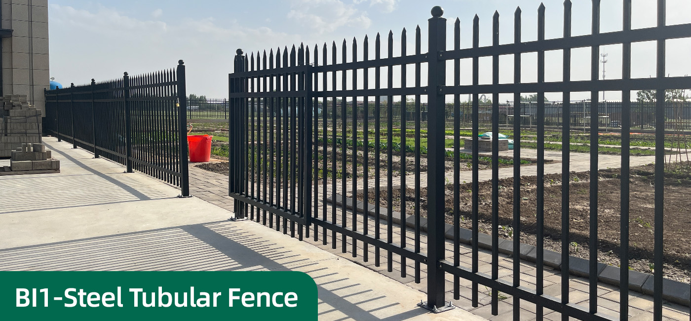
Perimeter protection establishes the physical boundary of an industrial site and helps manage access between the facility and surrounding areas.
The appropriate fence design depends on the required security function, site layout, environmental exposure and installation conditions.
Structural Components
A typical industrial perimeter fence may include:
- Welded mesh panels or other specified fence infill
- Steel posts and supporting profiles
- Panel-to-post connectors
- Ground anchors or concrete foundations
- Pedestrian and vehicle gates
- Galvanized or powder-coated components
The performance of the complete system depends on the compatibility of these components. A rigid panel alone cannot compensate for unsuitable posts, weak connections or inadequate foundations.
Choosing the Fence Structure
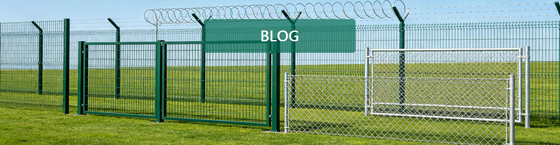
3D bending fence
Welded mesh panels with V-shaped bends provide a structured boundary for general industrial and commercial applications.
Double wire mesh fence
Double horizontal wire reinforcement may be suitable where the selected panel design requires additional stiffness.
358 anti-climb fence
Dense mesh openings can make climbing and cutting more difficult than with many conventional open-mesh fences. This configuration may be considered for restricted-access industrial facilities.
Chain link fence
Woven diamond mesh may be suitable for long boundaries and selected outdoor applications where flexible installation is useful.
Each product should be selected according to its actual structure and intended function.
Surface Treatment
Hot-dip galvanizing provides a zinc coating that helps protect steel against corrosion. Powder coating provides a decorative finish and an additional protective layer when applied over an appropriately prepared substrate.
A compatible galvanized and powder-coated system may be suitable for certain outdoor applications. The required treatment depends on the product, manufacturing process and environmental exposure.
Engineering Information to Confirm
Before finalizing a perimeter fence design, confirm:
- Fence height and panel width
- Mesh opening and wire diameter
- Post profile and wall thickness
- Panel connection method
- Foundation and anchoring requirements
- Gate dimensions and operating space
- Coating specification
- Applicable project requirements
A specific impact-resistance or service-life claim should only be used when supported by the relevant product specification and test evidence.
2. Modular Machine Guarding: Designing for Safe Access and Flexibility
Machine guarding establishes a physical boundary around hazardous machinery and automated production areas.
Its design should reflect the machine’s operating envelope, identified hazards, maintenance requirements and applicable machinery safety requirements.
Main Components
A modular machine guarding system may include:
- Welded mesh panels
- Steel posts and mounting brackets
- Fixed guard sections
- Pedestrian access gates
- Maintenance gates
- Mechanical latches
- Compatible safety interlocks where required
The complete system should be designed around the machinery layout rather than relying on a standard panel configuration for every application.
Modular Assembly
Standardized panels and compatible connectors can simplify assembly, replacement and certain layout modifications.
Potential benefits include:
- Consistent panel dimensions
- Coordinated post and fixing arrangements
- Easier replacement of damaged sections
- Flexible planning of access gates
- Simplified future expansion where permitted
However, modular construction does not automatically establish machine safety compliance. Any layout change must preserve the required guarding distances and safety functions.
Safety Gates and Interlocks
Where required by the risk assessment, an access gate may incorporate a compatible safety interlock connected to the machine’s safety-control system.
The interlock, control hardware and associated safety function must be suitable for the application and validated as part of the complete machine system.
A mechanical latch alone does not establish compliance with machine safety requirements.
Machine Guarding Design Checklist
Before ordering, confirm:
- Machine dimensions and operating envelope
- Required guarding boundary
- Panel height and mesh opening
- Post and fixing specifications
- Maintenance access points
- Gate dimensions and opening direction
- Interlock requirements, where applicable
- Applicable machinery safety requirements
Bendin can discuss compatible panel and gate configurations, while the machine integrator or responsible safety engineer should confirm the required safety functions.
3. Industrial Cable Management: Standardized Routing and Support
Cable management systems support and organize power, control, communication and instrumentation cables throughout industrial facilities.
A suitable cable routing design helps improve accessibility for inspection, reduce exposure to mechanical damage and simplify future maintenance.
Common Cable Management Products
Mesh cable trays
Open-wire trays provide a ventilated supporting structure for compatible cable installations.
Perforated cable trays
Perforated trays provide a supporting base with openings that may assist ventilation and drainage.
Solid-bottom cable trays
Solid-bottom trays provide a continuous supporting surface for suitable cable installations.
Cable trunking
Cable trunking provides a more enclosed route for selected cables.
Structural and Installation Considerations
The design should account for:
- Cable types and estimated quantities
- Total cable weight
- Tray width and side height
- Support spacing and span
- Material and surface treatment
- Connection and mounting accessories
- Cable separation requirements
- Environmental exposure
- Inspection and maintenance access
Tray load capacity depends on the selected design, support arrangement, span, connections and loading conditions.
Buyers should request the applicable technical data for the actual tray configuration rather than relying on a general description such as high load-bearing capacity.
Cable trays help organize wiring but do not eliminate every electrical hazard. The complete installation must meet the applicable electrical design and installation requirements.
4. Coordinating Interfaces Between the Three Systems
A major benefit of integrated planning is the ability to identify potential conflicts before installation.
For example, a perimeter fence may affect a vehicle access route, a machine guard may obstruct a maintenance aisle, or a cable tray may conflict with an equipment enclosure.
A coordinated project layout should identify these interfaces early.
| System | Main Interface | Design Information to Coordinate |
|---|---|---|
| Perimeter Fencing | Gates, access roads and site boundaries | Fence route, foundations, gate openings and access clearance |
| Machine Guarding | Machinery, operators and maintenance areas | Guarding boundary, gates, access clearance and safety functions |
| Cable Management | Equipment, supports and cable routes | Tray route, support locations, cable loading and maintenance access |
| Shared Installation | Floors, walls and other structures | Mounting points, service routes and installation sequence |
These systems should be coordinated without treating them as interchangeable safety measures. Each must satisfy the requirements relevant to its own function.
5. Typical Technical Specification Framework
Bendin can discuss customized product configurations according to product design, manufacturing capabilities and project requirements.
Perimeter Fencing
| Parameter | What to Confirm |
|---|---|
| Fence Type | 3D bending / double wire / anti-climb / chain link |
| Fence Height | Project-specific |
| Panel Width | According to the site layout |
| Mesh Opening | According to the intended function |
| Wire Diameter | Product-specific |
| Post Profile | Compatible with the selected panel |
| Surface Treatment | Galvanized / powder coated / other specified finish |
| Gates | Pedestrian / vehicle access |
| Foundations | According to site conditions and design |
Machine Guarding
| Parameter | What to Confirm |
|---|---|
| Guard Type | Full mesh / mesh with solid panel / punched panel |
| Panel Dimensions | According to the machine layout |
| Mesh Opening | According to the risk ass |